|
Space Vector - Pulse Width Modulation
|
 |
| Click to enlarge |
|
|
 |
| Click to enlarge |
|
|
 |
| Click to enlarge |
|
|
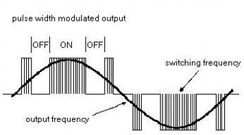
The above diagram shows a typical pulse width modulated output. The positive half of the cycle is formed by switching the solid state relay device that is attached to the positive DC link on and off at the switching frequency. The negative half of the cycle is formed by switching the solid state relay device that is attached to the negative DC link on and off at the switching frequency. The length of time of the on pulse determines the voltage of the output. The length of time the solid state relay device is off between pulses determines the frequency. The shorter the off time, the higher the frequency. The switching frequency determines the resolution of the pulse width modulated output. The higher the switching frequency, the higher the resolution. Higher resolution results in less efficient operation, common switching frequencies would be around 3000 to 4000 hertz. Smoother operation of the motor results from higher switching frequencies. The pulse width modulated output closely replicates the current waveform of typical AC, as seen in the above diagram.
|
|
Latest Technology - Sensorless Space Vector PWM
|
|